Railway Age Article
Complete Grade Separation at Birmingham, Ala.
[Note: this text has been reformatted to single column layout for ease of reading on the screen. Material on this page transcribed from Railway Age article, August 19, 1933.]
Track elevation permits conversion of the Louisville & Nashville station to the two level type
Marked improvements in the passenger station facilities of the Louisville & Nashville at Birmingham, Ala. comprised an important element of a $4,000,000 grade separation project recently completed by that road through the business district of that city. The grade separation was carried out jointly with the Southern, and with the Alabama Great Southern, which occupies a location adjoining the right of way of the L & N and crosses the tracks of the latter within the territory embraced in the improvement. The project included the installation of an interlocking plant, which controls the movements over the crossing, as well as through 26 switches in the trackage adjacent to the crossing.
In the Business Center of Birmingham
The situation giving rise to a demand for grade separation at Birmingham was typical of that encountered in cases where the business center of a city has grown up adjacent to railway lines and where comparatively level ground has favored the construction of grade crossings for all intersection streets except those that were cut off at or near the railway property lines to facilitate the development of adjacent land for freight and passenger stations, team tracks and industries. The gradual increase in both rail and street traffic eventually produced exceedingly objectionable conditions. For example, at the passenger station, which fronts on Morris Avenue, at the intersection with Twentieth street, serious interference with station operation was imposed by grade crossings at Twentieth and Eighteenth street, which passed directly over the two throats of the station layout. At the same time, any plan for grade separation at once introduced the prospect of decreased convenience in the arrangement of freight houses, team tracks and industrial service requiring direct access to city streets at grade.
Because of the physical conditions imposed early efforts at grade separation had been confined to the construction of a wooden viaduct to carry Twenty-second street over the tracks and driveways lying between Morris and Powell avenues. About 1918 this overcrossing was supplemented by another for Twenty-First street, but this was constructed of reinforced concrete, and in anticipation of grade revision, was placed at a sufficient elevation to permit a future raise of the track grades. A third viaduct, also of reinforced concrete, was built for Twenty-Fourth street in 1924.
Adopt Track Elevation Plan
Thus, the construction of viaducts for the three streets named above provided a satisfactory solution of the problem of grade separation east of Twentieth street while avoiding any disturbance of the existing relation of tracks to marginal streets, driveways, industrial plants, etc. However, as indicated by the provision made for contemplated changes in track grade, viaducts did not offer a satisfactory solution for grade separation from Twentieth street west, and the plan agreed upon by the railways and the city on October 31, 1928, called for track elevation, with underpasses for Twentieth, Eighteenth, and Fourteenth streets, and the replacement of the wooden viaduct at Twenty-Second street with a reinforced concrete structure.
Among other advantages, this plan permitted the development of a two-level plan for the passenger station, the superiority of which was readily appreciated after long experience at Birmingham with the shortcomings of a single-level layout for a through station. The problem of serving industry tracks, team yards, etc. was met by the retention of certain tracks on the street level between Fourteenth and Eighteenth streets, where they are not crossed by an public thoroughfare.
The adopted clear headroom of 14 ft. For the underpasses plus the required floor thickness, developed a difference in elevation of some 17 to 18 ft., of which from 3.5 to 5.5 ft. Was obtained by depressing the streets and the remainder by elevation the tracks, the maximum change of grade be9ing about 14 ft. With maximum run-off grades of 0.6 per cent, the change of grade extended over a distance of 6,200 ft. on the Louisville & Nashville and about 1,450 ft. farther at the west end on the Southern.
The Layout of the Elevated Tracks
(Click here to open a map and profile of the overall project -- original is two pages wide)
The elevated roadway was constructed to accommodate from three to four Alabama Great Southern tracks and from three to eight L & N tracks. As seen on the map, the project also involved the raising of a rather complex track layout at the crossing, including the construction of an incline for a Southern track connecting with tracks on the surface in Powell avenue. In addition, the L. & N. Also had a small yard between Fourteenth and Eighteenth streets, part of which was rebuilt on a 1.0 per cent grade descending eastward from the track elevation to the level of the streets. This serves as a supporting yard for the team tracks and industry service tracks between Fourteenth and Eighteenth streets.
West of Fourteenth street there was adequate right of way width to accommodated natural embankment slopes, but for almost the entire distance from the east side of that street to a point about 150 ft. west of Twenty-Second street it was necessary to provide retaining walls on both sides of the embankment. The walls built by the Alabama Great Southern are mainly of the cantilever type, largely on pile foundations. The Louisville & Nashville’s walls are largely of the counterfort type on spread footings, but some 290 ft. of precast concrete crib wall was installed east of Twentieth street, and east of that a wall of a cellular type was built on account of the low bearing power of the supporting soil.
The Underpasses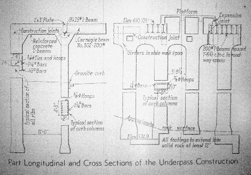
While the project involves only three underpasses, each of them is a large structure carrying 8 to 12 tracks and spanning streets from 80 to 100 ft. wide. Four spans are provided in each structure, with bents at the curb lines and the center of the street, and the construction is reinforced concrete except for the use of encased steel beams for track loading in the two roadway spans to obtain minimum floor depths for these longer spans. In the longest spans, namely, 38 ft. for the Twentieth Street underpass, 30-in., 200 lb. Carnegie beams were employed at a spacing of 1 ft. 6 ½ in. The sidewalk spans, and that portion of the roadway spans under the platforms, consist of reinforced concrete beams and slabs.
Design of Substructure
The design of the substructure was predicated on the requirements of the foundation, which is rock at widely varying depths. In many locations this was not more than 10 ft. below street level, but at other points it is 10 or more feet lower, with occasional crevasses extending to far greater depths. The intermediate supports, at the curb line and the center of the street, consist of bents made up of columns of rectangular section connected at their tops by half-ellipse arches to forma cross-girder or cap, these columns being extended to whatever depth was necessary to reach rock.
Attractive Portals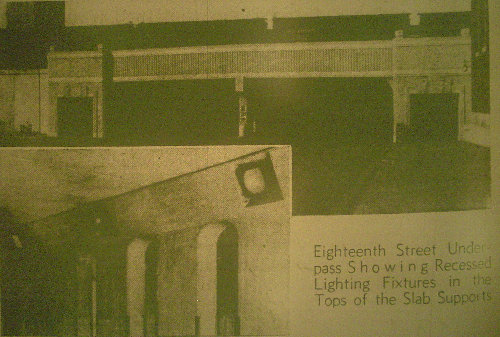
The abutments are also composed of rows of columns 3 ½ ft. by 1 ½ ft. in section (with the long dimension transverse to the street), which function also as vertical beams to take the lateral earth pressure of the embankments which is applied to a 10 in. curtain wall constructed monolithic with the columns. This wall extends only a short distance below the sidewalk level.
The underpasses are distinctive by reason of the exceptional attractiveness of the portal design and the excellent workmanship obtained in the casting of the moldings, panels and fine detailed ornamentation. Special care in the construction of the forms and the use of 1 ~ 1 ½ ~ 3 mix for the fascia concrete were responsible in part of the results obtained. The decks of these structures were covered with asphalt and fabric waterproofing, protected with asphalt plank. The lighting of these underpasses is out of the ordinary, special pains having been taken to obtain an evenly distributed and diffused illumination, but concealing the source from the eyes of vehicle drivers and pedestrians. All lights are enclosed in weatherproof metal boxes with hinged covers glazed with a diffusing glass, these boxes being set in recesses provided for them in the concrete of such depth that the cover is blush with the concrete surface. In the sidewalk spans these fixtures are installed overhead at a spacing of about 19ft. while in the roadway spans they are placed at intervals of 18 ft. in the filleted sides of the beams at the tops of the bents, as shown in one of the illustrations.
The Twenty-Second Street Viaduct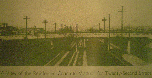
The most recently constructed of the three viaducts over the tracks, the one on Twenty-Second street, subsequent to its replacement has a total length of 1,050-ft. including the approach embankments. The structure proper has a length of 707.9 ft., center to center of end span bearings and consists of 17 spans from 32 ft. to 56.5-ft. long, center to center of piers. It is 70 ft. wide and accommodates a 56-ft. roadway and two 7-ft. wide sidewalks. The structure consists of T-beam spans, composed of 14 lines of girders and a slab floor4, supported on four-column bents and designed as continuous spans between double-bent expansion joints at intervals of two to four spans.
There
are maximum ascending grades of 4 per cent and 3.71 per cent from the north and
south ends, respectively, to a summit on two spans over the north runoff from
the track elevation, the determining feature of the design being a span of 56 ½
ft. over the four southerly of these tracks. To reduce the depth of girders to a
minimum in this span, which is the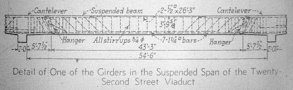 middle span of a group of three between
expansion bents, joints were introduced 5 ft. 10 ½ in. From each end, so that
the middle 44 ft. 9 in. Could function as simple suspended span supported by
cantilever extensions from the bents. The tension reinforcement in the bottom of
the girders is continued across these joints but all other bars were
interrupted. However, the most novel feature of the construction is the detail
of the support for the suspended girders on the cantilever girders. This
consists of a structural steel bracket concreted into the cantilever beams, that
was formed, as shown in the sketch, to provide a sort of halved joint affording
two bearings for the suspended span girders as well as two horizontal bearing
areas for the distribution of the load on the cantilever girders.
middle span of a group of three between
expansion bents, joints were introduced 5 ft. 10 ½ in. From each end, so that
the middle 44 ft. 9 in. Could function as simple suspended span supported by
cantilever extensions from the bents. The tension reinforcement in the bottom of
the girders is continued across these joints but all other bars were
interrupted. However, the most novel feature of the construction is the detail
of the support for the suspended girders on the cantilever girders. This
consists of a structural steel bracket concreted into the cantilever beams, that
was formed, as shown in the sketch, to provide a sort of halved joint affording
two bearings for the suspended span girders as well as two horizontal bearing
areas for the distribution of the load on the cantilever girders.
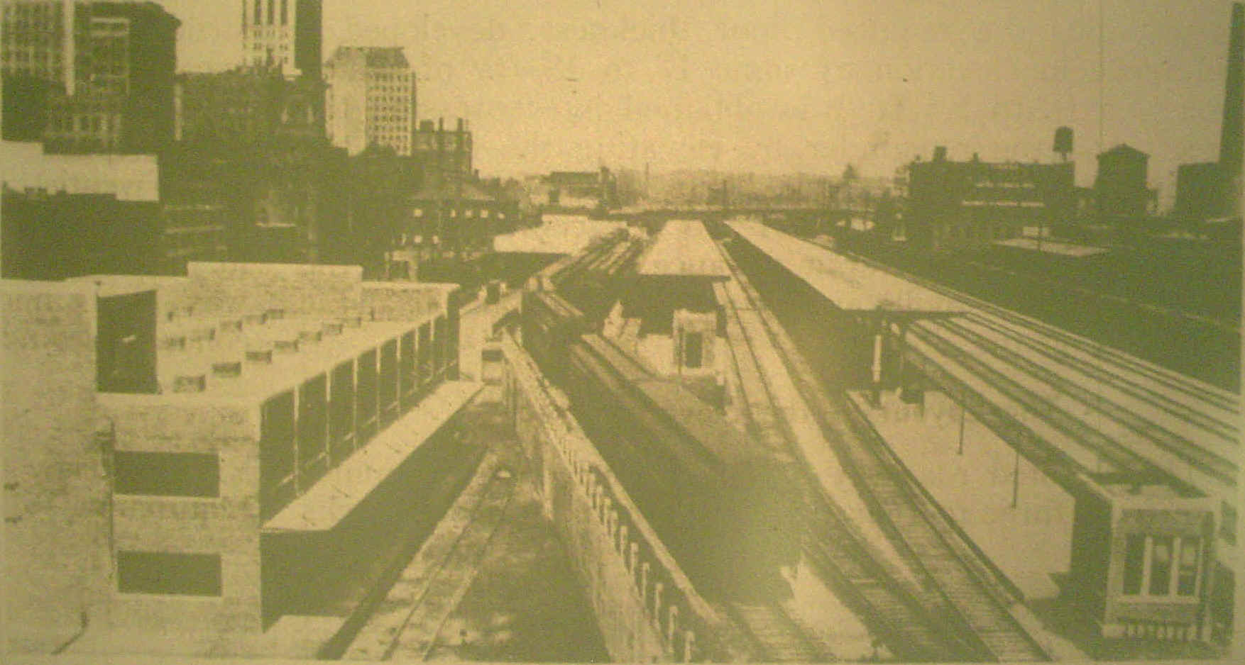
Improve Station Facilities
Previous to the separation of grades, the passenger station facilities of the L. & N. consisted of a station building about 213 ft. by 49 ft. fronting on Morris avenue at Twentieth street, supplemented by auxiliary buildings further west along Morris avenue and facing on the south on a train shed of 90 ft. span and 510 feet length. This sheltered five station tracks and the planked area between the tracks, and extended to the station building.
The elevated layout provides four passenger train tracks with two island platforms, and two coach tracks with a four-foot platform between them. These tracks are supported on an embankment enclosed on the north side by a retaining wall with its exposed face 64.9 ft. south of the old station. The transverse axis of the station track is at Nineteenth street, and a subway leading to four passenger stairways to the platforms was located there, while subways affording corresponding acce4ss to baggage-truck elevator were located 335 ft. to the east and 339 ft. to the west.
It was also necessary to amplify the existing baggage and express facilities, and this was done by providing a space for them 42 ft. 4 in. Wide by 440 ft. long, under the tracks from a point 18ft. 4 in. East of the passenger subway to a point 56 ft. 8 in. West of the west baggage subway. This was made possible by setting back the retaining wall and carrying the tracks on a reinforced concrete slab and column structure and enclosing the face of this undertrack space with a concrete curtain wall set flush with the remainder of the retaining wall. This space under the tracks is used to house a baggage room, express room, and mail room, and provide accommodations for station employees, coach maintenance forces , a room for conductors, and station master’s office and transformer and switchboard rooms.
(Click here to view a floorplan of the station area.)
A New Concourse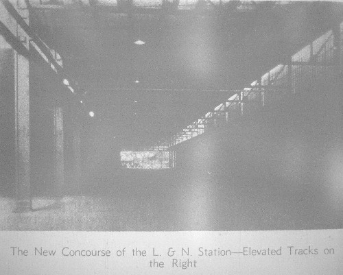
The open area between the retaining wall and the station buildings afforded ample room for the development of the necessary concourse for intercommunication between the station and the passenger-stairway subway and between the baggage, mail and express spaces and the east baggage-elevator subway. To do this, a concrete wall enclosing large areas of steel sash was constructed on top of the retaining wall, and steel roof trusses of 50-ft. span were erected at 25-ft. centers to span between this wall and the tops of the columns that formerly carried the north end of the old trainshed roof. Purlins spanning between trusses support precast concrete roof file.
The station platforms are of concrete and are covered with canopies having steel frames and cast-in-place concrete roof slabs covered whit pitch and gravel roofing. The problem of support for the canopy columns on filled ground was solved by setting them on concrete footings, each of which rests on two creosoted piles.
Another feature of the project was the construction of a reinforced concrete warehouse with brick exterior walls, 80 ft. by 180 ft., which is located between Eighteenth and Seventeenth streets. This building is two stories high, but the foundation and columns were designed to permit its eventual construction to a height of six stories. Other new facilities included a service building for mechanical department employees, a brick telegraph office, a brick building housing soil-can cleaning facilities, and a locomotive coaler and a cinder plant furnished by Fairbanks, Morse & Co.
The Interlocking
The railway crossing west of Fourteenth street is protected by an electric interlocking plant which was constructed under contract by the Union Switch & Signal Company, Swissvale, Pa. As seen on the map, the crossing embraces 13 individual track crossings, of which 6 have movable frogs. However, the plant also controls movements through 26 switches located within 850 ft. west and 1,150 ft. east of the tower, with the result that the plant operates 6 movable frog crossings 26 switches, 26 derails and 30 signals. The interlocking machine is a Union Type F, with 47 working levers and 16 spare spaces. The signals are of the semaphore type, using Union Style-T2 mechanisms and the switch machines are the Union Style-M2, operating on 110-volt direct current with Type-F circuit controllers mounted on separate concrete foundations. The installation also includes a train annunciator system providing push buttons on the station platforms for the use of conductors to notify the towermen of the departure of trains so that he may clear the requisite route.
Not only was it necessary to rebuild and rearrange all tracks serving the passenger train facilities, but it was also required to abandon the old source of water supply and obtain water from the local water company, construct a new high steel storage tank of 50,000 gal. Capacity and provide a new distribution system, including 12-in. Water columns as well as service boxes along the platforms. Corresponding provision was made for steam service, vacuum cleaners and battery charging. In addition, the telegraph, telephone and electric power lines, which had formerly been carried on poles, were placed in underground conduits between Seventeenth and Twentieth streets.
A Complete Construction Program
Because substantially all of the area affected by the construction work is covered by tracks at a close spacing, it was necessary to carry on the work in accordance with a carefully prepared schedule that insured adequate provision for the handling of traffic at all times, and because the tracks of the two roads are adjacent, it was necessary to elevate their tracks concurrently. In general, the plan involved the construction of the embankments and structures in long9tudinal strips, while service was maintained on tracks continued in use on the surface until the transfer could be made to tracks on the elevation. Also, because the city insisted on a minimum of interference with pedestrian and vehicle traffic, it was decided to complete the work on the Twenty-Second street viaduct first, before blocking Fourteenth street, and complete the underpass at that street before closing Eighteenth and Twentieth streets.
Accordingly, after completing the Twenty-Second street viaduct, the second stage of the project was to build the retaining walls between Fourteenth and Eighteenth streets, and raise the tracks across Fourteenth street under traffic to final elevation, completing the run-off on the west end and introducing a temporary run-off on the east at a 0.6 per cent grade which reached the original track grade at Eighteenth street. Following this, falsework was driven at Fourteenth street and the excavation made to permit the building of the underpass.
The next step was to block Eighteenth and Twentieth streets, handle L. & N. passenger trains to the east of the station on a track north of the L. & N. freight station and to the west of the station on a yard track that made a connection with the main line near Fourteenth street. In addition, the L. & N. confined freight trains to its northbound main track, while the A.G.S. diverted all train movements to its southbound main track. These two tracks were adjacent at about the middle of the proposed underpasses, and the removal of all other tracks permitted work to proceed on the construction of the two underpasses except for the space in the middle occupied by these two operated tracks and a short section at the north end of the Eighteenth street structure which had to be omitted to provide room for the temporary connection to the L. & N. station from the west.
While the work on the underpasses was in progress, the retaining walls east of Twentieth street were constructed and the grading was done on the approach fills to those parts of the underpass3es then under construction. During this period, work proceeded also on those parts of the L. & N. passenger subways that did not interfere with passenger service under the trainshed.
Transfer Traffic to High Level
After this stage of the work was completed, L. & N. and A.G.S. freight traffic was diverted to the high level, thus permitting the middle section of the underpasses to be constructed. While this was being done, the south butterfly shed and platform at the L. & N. station were constructed, the adjacent fills made and the tracks laid, which permitted the A.G.S. to complete its part of the work and provided the L. & N. with two main tracks and three station tracks. The L. & N. then diverted its passenger traffic to the high level which permitted the construction of the north portal of the Eighteenth street underpass, the construction of the service building under the station tracks and the retaining wall between Eighteenth an d Twentieth streets. The remainder of the work was continued with no interference with train movements.
The improvement work at Birmingham was designed and built under the direction of an engineering commission created by the grade separation agreement and consisting of A. J. Hawkins, city engineer of Birmingham; B. Herman, chief engineer of the Southern; and Edward Wise, Jr., special engineer of the Louisville & Nashville, representing W. H. Courtenay, chief engineer. The cost of the grade separation work was divided equally between the city and the railroads, each paying one half the cost of the work on its property. Each railway designed and built its own retaining walls and handled the grading on its own property with company forces but the plans for the Twenty-Second street viaduct and the underpasses, as well as the station facilities were prepared by the Louisville & Nashville, which also supervised the construction under contract of these portions of the project. J. W. Hoyt was resident engineer for the Louisville & Nashville.
The contractors participating in the project included Millsap & Parker, Birmingham, on the Twenty-Second street viaduct; the Gould Construction Company, Nashville, Tenn., on the Fourteenth street underpass; the Southern Construction Company, Birmingham, on the two other underpasses and other station structures, such as the butterfly sheds, concrete platforms and paving, and retaining walls; the Foster-Creighton Company, Nashville, on the warehouse building and the service building under the station tracks; A. J. Honeycutt, Birmingham on the passenger and baggage subways; D. T. Underwood, Birmingham, on the concourse shed and several small buildings; Walter T. Weaver, Birmingham, on the retaining walls between Fourteenth and Eighteenth streets; the Otis Elevator Company, Atlanta, on the elevators; the Union Signal Construction Company, Swissvale, Pa., on the interlocking work, and various other contractors. About 50 separate contracts were let during the course of the project.