Basic Benchwork Criteria
 |
| Building simple, sturdy benchwork following a repetitive pattern of
component parts (elements) makes for a nicely done railroad. Most
of what you need to know is shown in the graphic above and described in
the narrative below. Develop a basic set of "parts" or
basic elements and use them over and over again and you will do fine.
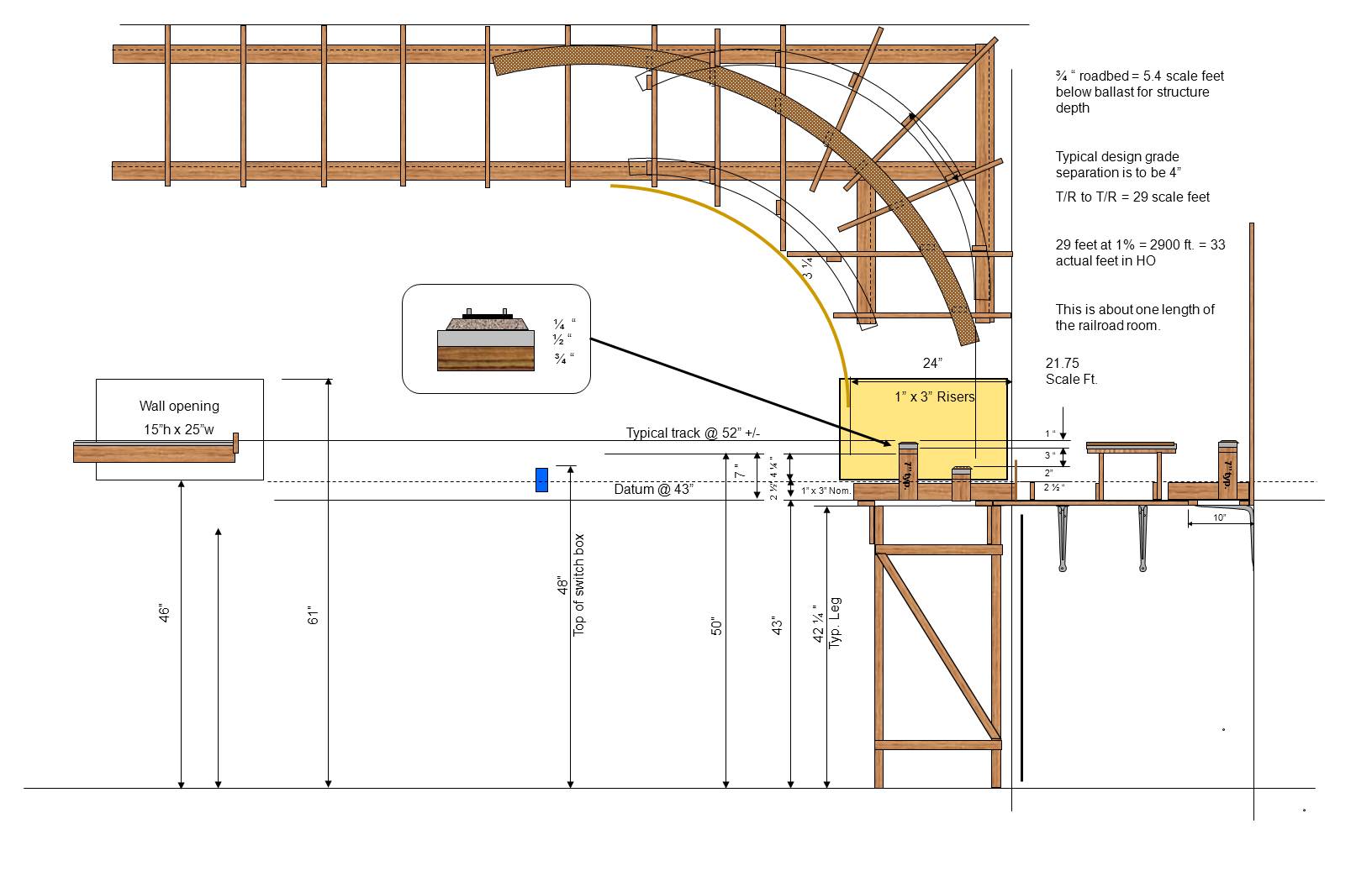
One "prime directive", if you can manage it, is DO NOT saw lumber/plywood/homasote in the layout area, if you are able to avoid it. It makes for a far cleaner layout area for the life of the railroad. If your layout is in the garage, do your sawing in the driveway wiht the door closed, if at all possible. This graphic shows the basic benchwork elements using L-girders. The railroad is essentially free standing, using 2 x 2's for legs, and 1 x 2's for diagonal bracing. L-girders are generally 1 x 4 webs (vertical part) and 1 x 2 flange, (horizontal part). Use L-girders and NOT T-girders. The "bents" (legs and diagonals) are spaced as far apart as the L-girder will allow comfortably. Our bents are about 8' maximum spacing. The joists are 1 x 3's which were readily available at Lowe's or Home Depot. I am a proponent of this open grid style benchwork. Note that yards or other flat spaces, like a large industry, may perfectly well have flat areas made from plywood sheet and homasote. You don't have to use trackboards everywhere. I tend to put cork down in yards for appearance and less likely in a large industrial area like my steel works. I could likely have used more "cookie cutter" construction in some areas of the railroad, but once I started making trackboard/roadbed I pretty much used it everywhere. I have been using extruded "blue" foam to fill in areas around the open trackboards if the terrain is going to be in small components. On my big Red Mountain, I used cardboard grid to fill in the terrain since most of it is NOT flat. So, use what works best for the space you are working on. My scenery is FAR from complete and we are running trains with formal operations. So, I am not necessarily a good example to follow. Note that I am 6'-4" tall and the layout is built for me. Track height above the floor ranges from about 51" to 61". It is not so convenient for operators who are not as tall as I am, but I have sturdy foot stools for them to use. If the layout has a fault it is that there are switching locations that are more than 2 feet from the edge of the layout. That is not a good thing, but needed to be done - try to minimize it if you can. And the layout height adds to the problem or "reach" for shorter operators. I do find that well planned switching moves, using the Kadee delayed action can simplify many of these problems. End of lecture. Roadbed is built up of 5/8" plywood, try to use 5 ply (B/C surface is adequate), with 1/2" Homasote for a subroadbed and cork roadbed under the track. Riser spacing doesn't generally exceed about 12". Note how you may add joists in the corners to keep the riser spacing to 12" maximum. We are able to buy Homasote in Birmingham, AL but only a commercial supply house carries it. It was about $38 per sheet in 2010. I honestly don't understand the layout owners who buy 3/4 birch plywood that is very expensive as well as expensive dimensional lumber. I use the least expensive clear lumber I can find at the home center, generally what they call "whiteboard" lumber. Pick your own that is straight and free of knots and defects - Lowes calls it "whitewood softwood board" lumber. Consider humidity vs. wood quality - the more humidity variation, the better quality lumber you should buy: clear kiln- dried lumber is the goal, not oak or poplar species which is expensive. Note that if you are fortunate enough to have air conditioned space the quality of plywood and lumber is less important - air conditioning also means that the layout will be cleaner. Homasote is VERY humidity conscious. If you are not air conditioned and use homasote (a really good sound deadener) then I WOULD paint it to seal it before you lay track. I didn't paint it, I have A/C and it is a very minor issue that I didn't paint it. The only part of the benchwork that is glued is the L-girders, which are generally glued and screwed. All screws are common "drywall screws", generally using 1 1/4" for joining "1 by" material and 1" screws for joining the Homasote to the plywood. Many people want to glue the Homasote to the roadbed but I did not. Instead the Homasote is screwed to the plywood about every 6" for single track. Yes, these screws are hidden under the cork. We did use a pilot bit for the drywall screws. In other words, the piece of wood closest to the screw head has a pilot hole drilled through it; the receiving member generally does not. This helps make good tight connections with a minimum of work. We did use longer screws (1 5/8") for connecting the L-girders to the 2 x 2 (nominal) legs, and we did mostly drill a pilot hole at least partway into the legs. Nearly every other screw is accessible for removal and this is an important rule to follow. You WILL find a need to move or adjust benchwork components in the future. Some parts of the layout are narrow enough, about 12" to be supported by common pressed steel shelf brackets attached to the studs. When this method is used, a pair of 1 x 2's spans the shelf brackets and fills the role of the "top of the L-girder". That is, the 1 x 2 is available to support the short 1 x 3 joists, which in turn, support the roadbed risers. The holes in the shelf brackets are adequate to locate the screws connecting the 1 x 2 to the bracket. I actually used 3rd PlanIt software to lay out the benchwork in 3D. This may seem extreme but it paid off when developing the vertical components - the track/roadbed risers. By setting the datum in the design software to be the top of the joists, the track elevation could be made to provide the length of the risers. In other words, by setting the roadbed thickness, and measuring from the top of the joists, the "track elevation" is given by the software as the length of the riser. The software enables you to set the grades of the track - that is, the percentage rise or fall of the track as you go uphill or downhill. The risers in turn are going to need to be cut accurately and there are a lot of them to cut. To make this work, use the software with the benchwork on a separate level, so it can be turned on and off. Then when cutting risers for a particular part of the railroad, turn on the benchwork level and show it "behind" the track. Select a joist location, use the "elevation" command and click on the track at the location of the joist -- riser height is provided between the top of the joist and the bottom of the plywood track board. Bear in mind that the gradient, or steepness of the track, should be a minimal amount, ESPECIALLY if you are using steam locomotives. On the BDMRR the maximum grade is 2% on the Red Mtn. mine branch and about 1.5% in a couple of spots on the mainline. A two percent grade is about 1/4" rise or fall per foot of track; one percent is about 1/8" rise per run. Railroads spend great amounts of money to avoid grades much over 1%, and want lower if they can manage it. Plan your layout carefully to avoid grades over 1%. On thing about the risers that worked well is that they are flush with the top of the joists (that is, they "sit" on top of the joists) and use a "standard" 5 inch "gusset plate" to connect the riser to the joist. We kept a supply of these gusset plates ready with pre-drilled pilot holes - 2 pairs of diagonal pilot holes. Once the riser location was known, the gusset could be placed, clamped and screwed to the joist. This gave a good solid place to hold the riser and if needed clamp it and screw it in place. It seems a bit redundant but it sure makes it easier to built and particularly to adjust later. One of the most useful tools we bought and used a great deal is a pocket screw hole jig. Mine cost $30 at Home Depot and includes the jig and a special bit. We ended up using regular drywall screws rather than the special screws that come with the jig. I mounted it on the work bench next to the "chop saw" (see below) so that I could drill pocket holes in risers when I cut them. The jig is used to connect a piece of wood end-on to another piece. For example, the top of the riser could be screwed to the bottom of the plywood track board by using the pocket holes. This gives a good strong connection between the risers and the roadbed. There were other places where these pocket hole connections were very useful, such as the support system for the backdrop. If there were one other tool that I would recommend very strongly for a moderate to large size layout it would be a "chop saw". This is a compound miter power saw. The value is square cuts that may be quite accurate as well as angle cuts. I doubt we used the compound miter feature much but if you are going to get the saw might as well get a compound. This means that the saw may be rotated horizontally as well as in a vertical plan. For the amount of lumber you are going to need to cut, quickly and accurately, I think that the saw is a really good investment. I also have a table saw, and it is very useful, but if I had to choose between the two I would get the chop saw first. Both are tools you will use for a lifetime, although I had power hand tools early and didn't get these table/bench saws till I started this layout at age 57. Well built benchwork that is neatly done will be a great asset to your railroad. I have some lumber in the layout that is on its 3rd layout but strive to make a good neat job of your benchwork. It does not have to be HEAVY, it just needs to be STIFF. Stiffness is achieved with diagonal bracing on the bents - the diagonals may be 1 x 2's and provide all the stiffness you need. |